
Flanges · ASME B16.5 · 2026
Metal Forge India manufactures and exports flanges from Mehsana, Gujarat, with HQ in Mumbai (since 1979). This page is the comparison engineers use before they open a B16.5 table: which type, why, and what else must be on the purchase order. Product pages: socket weld flanges, weld neck flanges, slip-on flanges.
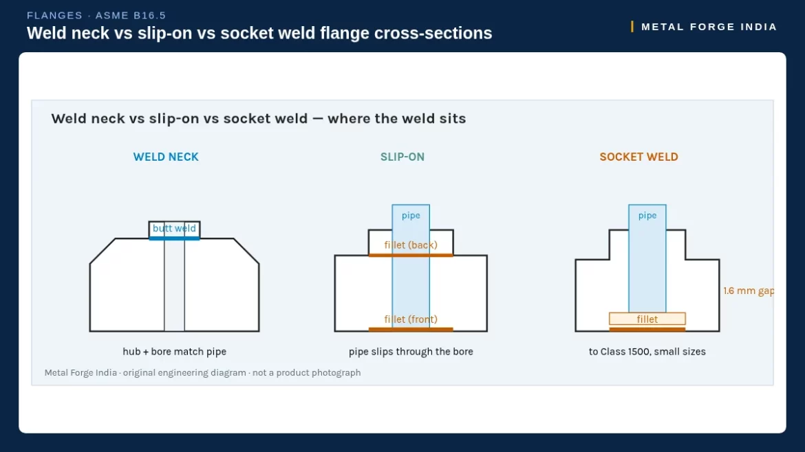
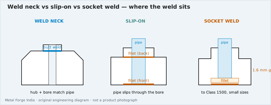
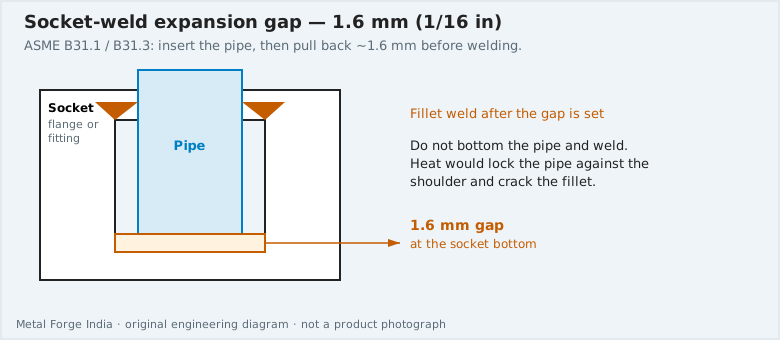
A weld-neck flange uses a butt weld and a tapered hub. A slip-on uses two fillet welds. A socket-weld flange takes one fillet after a 1.6 mm gap at the socket bottom (ASME B31.1 / B31.3). Socket-weld hubs run through Class 1500 in small sizes. Pick the hub from the piping class.
Metal Forge India has manufactured flanges, fittings and pipe spools since 1979. Head office: Mumbai. Factory: Mehsana, Gujarat.

Download flange comparison spec chart (PDF)
Socket weld vs slip-on vs weld neck — comparison
- Butt weld to pipe (full penetration)
- Best fatigue / bending strength
- Default on process lines
- Any B16.5 size / class
- Pipe inserted through the bore
- Cheaper, easier fit-up
- Two fillets when specified
- Not for severe cyclic service
- Pipe sits in a recessed socket
- Small-bore (typically ≤ NPS 2–4)
- One fillet at the hub
- Crevice at the shoulder
| Weld neck | Slip-on | Socket weld | |
|---|---|---|---|
| Joint | Butt weld, tapered hub | Fillet(s) at hub / bore | Fillet at hub after socket fit |
| Typical size | All B16.5 NPS | All B16.5 NPS (as class allows) | Small bore, often NPS ½–2 |
| High pressure / temp | Yes — preferred | Limited | Generally no |
| Radiography of joint | Weld is RT-able | Fillet not RT in the same way | Fillet not RT in the same way |
| Bore match to pipe | Specified to pipe ID / SCH | Bore larger than pipe OD | Socket ID per B16.5 |
| Fatigue | Best of the three | Worse than WN | Crevice + fillet — not for vibration |
When to use each type
Weld neck
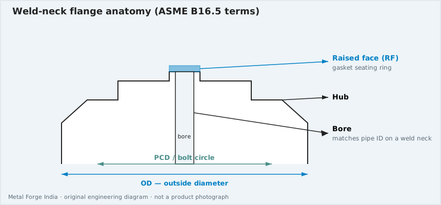
Specify WN whenever the line is process-critical, the class is 300 and above (and often 150 on hydrocarbons), the temperature cycles, or the owner spec already says “WNRF.” The hub tapers the thickness from flange to pipe so the butt weld sits away from the bolt circle. More on types and uses: weld neck flanges — types, features, uses.
Slip-on
Slip-on (SO) is a fabrication convenience: the pipe is slid through, squared, and fillet-welded. It is common on low-pressure utilities, water, and some tank nozzles. It is a poor substitute for WN on steam, hydrogen, or sour process. Alignment is easier than WN; integrity is not equivalent.
Socket weld
Socket weld (SW) flanges are a small-bore solution. The pipe is inserted until it bottoms, withdrawn ~1.6 mm (1/16 in) per good practice so the fillet is not cracked by expansion, then welded. The remaining crevice collects corrosive fluid — one reason high-pressure and sour specs forbid SW. Broader definition: what are socket weld flanges. Why not high pressure: socket weld flanges at high pressure.
ASME B16.5 pressure classes
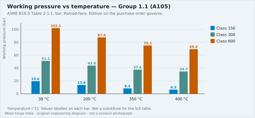
B16.5 classes are 150, 300, 400, 600, 900, 1500 and 2500. The allowable pressure at a given temperature depends on the material group (for example carbon A105 vs stainless A182 F304 vs F316), not on the flange type. A Class 150 F316 WN and a Class 150 F316 SW share the same P-T rating in B16.5; they do not share the same joint integrity. We do not paste the copyrighted P-T tables here — use the current ASME B16.5 edition for design. On the RFQ, write class + material + temperature, not “150 lbs” twice.
B16.47 Series A (MSS SP-44 heritage) and Series B (API 605 heritage) cover NPS 26 and above. Socket weld does not apply there. See the flanges hub for type navigation.
Key dimensions (indicative, Class 150 RF, ASME B16.5)
The figures below are commonly published Class 150 raised-face values used for envelope checks (mm). Confirm against the current B16.5 before cutting or modelling. Hub length and bore still depend on type (WN vs SO vs SW) and on pipe schedule for WN bore.
| NPS | Flange OD (mm) | Bolt circle (mm) | Bolts n × dia | Typical use of this class |
|---|---|---|---|---|
| 1 | 108 | 79.4 | 4 × ½ | Small-bore process / utility |
| 2 | 152 | 120.7 | 4 × ⅝ | Utility and instrument headers |
| 4 | 229 | 190.5 | 8 × ⅝ | Very common process size |
| 6 | 279 | 241.3 | 8 × ¾ | Headers, pumps |
| 8 | 343 | 298.5 | 8 × ¾ | Transfer lines |
| 12 | 483 | 431.8 | 12 × ⅞ | Main process |
Indicative Class 150 only. Class 300 and above: thicker flanges, larger bolt circles, more / larger bolts. WN hub length is longer than SO/SW. Not a substitute for ASME B16.5.
For Class 300, 600, 1500 and 2500 the OD and bolt pattern grow quickly — a 2″ Class 2500 is a completely different forging from a 2″ Class 150. Always pair NPS with class on the isometric and the RFQ.
Facings: RF, FF and RTJ
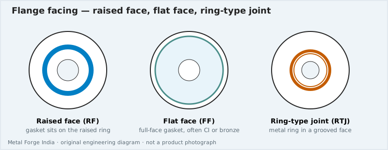
Type (WN/SO/SW) is independent of facing. Raised face (RF) is the default on most process classes. Flat face (FF) mates to FF equipment (often cast iron — do not bolt RF to FF without an engineering note). Ring-type joint (RTJ) shows up on high-pressure and some sour classes; the groove dimensions are in B16.5 and the ring number belongs on the isometric. A socket weld RTJ exists in the standard for small bore; it is still a fillet joint. Mixing RF and RTJ on a pair is a leak waiting for hydro.
Bolting, gaskets and what is not on the flange PO
A flange RFQ is not automatically a stud-bolt RFQ. If fasteners ship with the flange, say so (grade, length, coating). Spiral-wound vs RTJ rings vs sheet gaskets follow the facing. We will not assume PTFE on every RF or a 316 spiral wound on every class 300. Fastener hub: fasteners.
Class 150 vs 300 vs 600 — a buyer’s translation
Class is not “pounds of water.” It is a B16.5 designation. Roughly, Class 150 is common on low-pressure utilities and some process; Class 300 is a very common oil & gas default; Class 600 and above show up on higher-pressure steam, gas and well-connected lines. The jump in forging weight and bolt size is nonlinear. Do not “upgrade” a Class 150 isometric to Class 300 in procurement to be safe — the mating equipment, gaskets and supports all change.
Class 400 exists in B16.5 but is uncommon in many owner specs (they jump 300 to 600). Class 900 / 1500 / 2500 are specialised. If the RFQ says “1500 lbs SW flange, 8 inch,” we will query it: socket weld at that class and size is usually the wrong type.
Materials that actually sit under these three types
Carbon steel A105 is the default CS forging. Stainless and alloy use ASTM A182 grades (F304/F316/F11/F22/F51 as specified). Low-temperature carbon (A350 LF2) is a different spec — say LF2 when the class is LTCS. Nickel alloys (625, 400, C276) are not A105 and not automatically A182 F-grades; use the nickel product URLs. IBR applies to some Indian boiler flanges — see the IBR approved flanges page rather than assuming every WN is IBR.
Application by industry
- Oil & gas / petrochemical: WN on process; SW on some small-bore instrument air or lube oil if the class allows; SO rarely on hydrocarbons.
- Power / steam: WN. SW and SO are the wrong default on steam.
- Water / HVAC: SO is common at low class; WN still used at pump suctions/discharges when the spec says so.
- Small-bore stainless skids: SW flanges and B16.11 fittings are often used together — still check crevice and hygiene requirements.
Seven-type overview: what is a flange and its 7 types. Lap-joint mates with a stub end, not with these three hubs.
Request WN, slip-on or socket weld flanges
State type, NPS, class, facing, grade and quantity. quality system. / when the project requires them.
Common specification mistakes
- Writing “150 lbs” twice in a class list and skipping 1500 — a historic error on some templates. Use the B16.5 class set once.
- Ordering SW flanges for steam because they are cheaper than WN.
- Matching a slip-on to a WN on the other side of a gasket without checking bore and facing.
- Calling every stainless flange “A182 F304” when the pipe is F316L.
- Forgetting RTJ groove finish on a class that the isometric already shows as RTJ.
- Ordering from a location page instead of the product page. Use /flanges/ and the type children for type, size and class.
If you are still at “what is a flange?” start with seven types and then return here for the three-way joint decision. If you already know you need WN, skip to the weld neck product page and send size/class/grade.
How this comparison relates to other flange types
Blind flanges close a line; they can be WN-style (raised hub) or a plain blind. Threaded flanges are a fourth joining method (no weld) with their own limits on temperature cycling. Lap-joint flanges float over a stub end and are a maintenance choice, not a strength upgrade. Those types are on the flanges hub and in seven types. This article stays on SW vs SO vs WN because that is the decision that most often appears on small-bore vs process isometrics.
RFQ examples
- Quotable: “6″ 300# WN RF ASTM A105, 20 pcs, 3.1, FOB Mundra.”
- Quotable: “1″ 3000 SW RF A182 F316L, 80 pcs, 3.1, CIF Houston.”
- We will query: “8″ 1500# socket weld flange” — type vs class mismatch is likely.
- We will query: “slip-on, RTJ, class 150, 24 inch” — unusual pairing; confirm facing.
Glossary
- Hub — the axial portion of the flange that meets the pipe (tapered on WN, short on SO/SW).
- Bore — inside diameter; on WN it should match the pipe ID/schedule.
- Bolt circle — PCD of the bolt holes; class-dependent.
- Raised face height — 2 mm vs 7 mm depends on class in B16.5; do not ignore it in a 3D model.
- Crevice — the gap at a socket shoulder; corrosion and fatigue concern.
FAQ — socket weld, slip-on and weld neck
What is a socket weld flange?
A socket weld flange has a recess (socket) into which the pipe is inserted, then a fillet weld is applied around the hub. It is an ASME B16.5 type used mainly on small-bore (typically NPS ½–2, sometimes to 4) piping where a buttweld hub is not required.
Socket weld vs slip-on flange — which is stronger?
A slip-on uses one or two fillet welds on a pipe that passes through the bore. A socket weld uses a single fillet at the hub plus a defined bottom clearance. Neither matches a weld-neck butt weld for high pressure, high cycle or severe temperature. For small-bore instrument and utility lines, socket weld is often preferred to slip-on because of the socket fit-up.
When should I use a weld neck flange?
Use a weld-neck (tapered hub, butt-welded to the pipe) for process lines, high pressure, high temperature, cyclic service and wherever the piping class already names WN. It is the default high-integrity flanged joint in oil & gas and power.
What ASME standard covers these flanges?
ASME B16.5 covers NPS ½–24 in Classes 150, 300, 400, 600, 900, 1500 and 2500 (material-group dependent). Larger diameters use B16.47 Series A or B. Socket weld flanges in B16.5 are limited in size; they are not a B16.47 item.
Can I use a socket weld flange on high-pressure steam?
Usually no. High-pressure steam and other severe services specify weld-neck. Socket weld also leaves a crevice between the pipe end and the socket shoulder — a corrosion and fatigue concern. See also our note on why socket weld flanges are not used at high pressure.
Do dimensions change with pressure class?
Yes. Thickness, hub, bolt circle, bolt size and raised-face height change with class. OD of the flange also changes. Always quote NPS + class + facing, not NPS alone.
Socket weld flange vs weld neck — can I mix them on one line?
Only if the piping class allows it (for example WN on the header and SW on a small-bore take-off). Do not mix facings (RF vs RTJ) on a mating pair.
What should an RFQ include?
Type (WN / SO / SW), NPS, class, facing, bore (std vs specified ID), material grade (A105, A182 F304/F316, etc.), quantity, and any NACE / IBR / 3.2 requirement.
Key takeaways
- Weld neck = butt weld + hub; use it on process lines.
- Slip-on = fillet convenience; not a WN substitute in severe service.
- Socket weld = small-bore only; crevice and fillet limit its use.
- Class and material group set P-T ratings, not the flange type.
- RFQ: type + NPS + class + facing + grade.
Related specifications
Class 300 to 2500 — OD and bolt circle
Class 150 is already in the comparison table. Higher classes grow OD, thickness and bolt count. Hub length and RF height also change; those columns are in B16.5 and are not copied in full here.
ASME B16.5 Class 300 — OD / bolt circle (indicative mm)
| NPS | OD | PCD | Bolts n × dia (in) |
|---|---|---|---|
| 2 | 165.1 | 127.0 | 8 × 5/8 |
| 4 | 254.0 | 200.0 | 8 × 3/4 |
| 6 | 317.5 | 269.9 | 12 × 3/4 |
| 8 | 381.0 | 330.2 | 12 × 7/8 |
| 12 | 520.7 | 450.8 | 16 × 1-1/8 |
ASME B16.5 Class 600 — OD / bolt circle (indicative mm)
| NPS | OD | PCD | Bolts n × dia (in) |
|---|---|---|---|
| 2 | 165.1 | 127.0 | 8 × 5/8 |
| 4 | 273.0 | 215.9 | 8 × 7/8 |
| 6 | 355.6 | 292.1 | 12 × 1 |
| 8 | 419.1 | 349.2 | 12 × 1-1/8 |
| 12 | 558.8 | 489.0 | 20 × 1-1/4 |
ASME B16.5 Class 900 — OD / bolt circle (indicative mm)
| NPS | OD | PCD | Bolts n × dia (in) |
|---|---|---|---|
| 2 | 215.9 | 165.1 | 8 × 7/8 |
| 4 | 292.1 | 235.0 | 8 × 1-1/8 |
| 6 | 381.0 | 317.5 | 12 × 1-1/8 |
| 8 | 469.9 | 393.7 | 12 × 1-3/8 |
| 12 | 609.6 | 533.4 | 20 × 1-3/8 |
ASME B16.5 Class 1500 — OD / bolt circle (indicative mm)
| NPS | OD | PCD | Bolts n × dia (in) |
|---|---|---|---|
| 2 | 215.9 | 165.1 | 8 × 7/8 |
| 4 | 311.2 | 241.3 | 8 × 1-1/4 |
| 6 | 393.7 | 317.5 | 12 × 1-3/8 |
| 8 | 482.6 | 393.7 | 12 × 1-5/8 |
| 12 | 673.1 | 571.5 | 16 × 2 |
ASME B16.5 Class 2500 — OD / bolt circle (indicative mm)
| NPS | OD | PCD | Bolts n × dia (in) |
|---|---|---|---|
| 2 | 235.0 | 171.4 | 8 × 1 |
| 4 | 355.6 | 273.0 | 8 × 1-1/2 |
| 6 | 482.6 | 368.3 | 8 × 2 |
| 8 | 552.4 | 438.2 | 12 × 2 |
| 12 | 762.0 | 619.1 | 12 × 2-3/4 |
ASME B16.5 millimetre drilling tables for the NPS shown. Class 2500 NPS 12 OD is 762 mm (30.00 in) per B16.5-2020 Table 21.
Which hub columns must the RFQ still name?
OD and PCD do not replace hub diameter X or length Y through-hub. Those B16.5 columns belong on the datasheet. Full hub tables for NPS ½–24 are not copied here.